CSSC - EP.1 : The Starting Point
Available in 繁體中文
Since the blog was set up relatively late, a lot of content has accumulated, which I’ll be catching up on in the next few posts.
The designs for the components I’m about to introduce were actually implemented on breadboards several years before this project even began. This time, with the school’s final project deadline approaching, I decided to revisit my previous work and incorporate new ideas, embarking on a brand-new CPU project.
.
Basic Architecture Design
To meet the assignment deadline, I decided to adapt the designs I had previously implemented on breadboards. The core reference, and the inspiration for most of the design, comes from Ben Eater’s 8-bit breadboard CPU project.
Currently, two main implementation points have been completed:
- ALU (same as Ben Eater’s ALU, but without flags implemented yet)
- Register A, B (same as Ben Eater’s Register A, B)
An ALU (Arithmetic Logic Unit) is a hardware component primarily responsible for processing arithmetic and logical operations. Registers are a type of computer memory used for storing and accessing data.
In our design, Register A and B are used to store the two values for addition and subtraction operations. The ALU currently only supports addition and subtraction, but we can employ some clever tricks to implement other functions, such as bitwise shifts.
Our ALU currently supports addition and subtraction. It does not include bitwise AND, OR, or comparison operations. These operations would typically use Register A and B to store data during computation. After the ALU performs an operation, the result can be stored in a result register for subsequent program use. Additionally, we plan to expand the ALU’s functionality to include operations like multiplication and division.
In summary, the ALU and Registers are indispensable components in our computer design. They provide fast, efficient computational capabilities, forming the foundation for subsequent program execution.
.
Why not use breadboards?
When conducting circuit experiments using breadboards, an important factor to consider is their inherent instability. Because breadboard contacts are not fixed, inserting or removing electronic components, or even during transport, can lead to poor contact, causing the circuit to malfunction.
Therefore, to avoid contact issues caused by the instability of breadboards, I decided to use direct soldering, soldering the electronic components onto a perfboard (general purpose PCB). This ensures greater circuit stability and reliability, allowing for long-term use and making the circuit less susceptible to issues during transportation, which is crucial for delivering it to school for the assignment.
.
Design Implementation

The image above shows the final assembled result.
The metal box cropped out on the left side of the image is a 5V 10A power supply.
.
To make the overall storage more convenient, I decided to change the computer’s architecture to a tower case design after testing the functionality of each board. This architecture allows the motherboard, graphics card, hard drives, and other main components to be combined and placed within a single tower-shaped enclosure, making storage much more convenient.
However, such an architecture presents some challenges. Firstly, because all computer components are sealed within the tower case, debugging becomes less convenient. If a problem arises, we need to open the entire case to inspect the internal components. Additionally, heat dissipation in a tower case is more challenging, requiring thorough consideration during the design phase.
Despite these difficulties, I chose to sacrifice debugging convenience for the compactness of the tower case architecture. Because in our project, storage convenience is a very important factor; we need to arrange the computer components within the minimal space to achieve the best storage effect.
.
Component Introduction
Next are the actual images of the components.
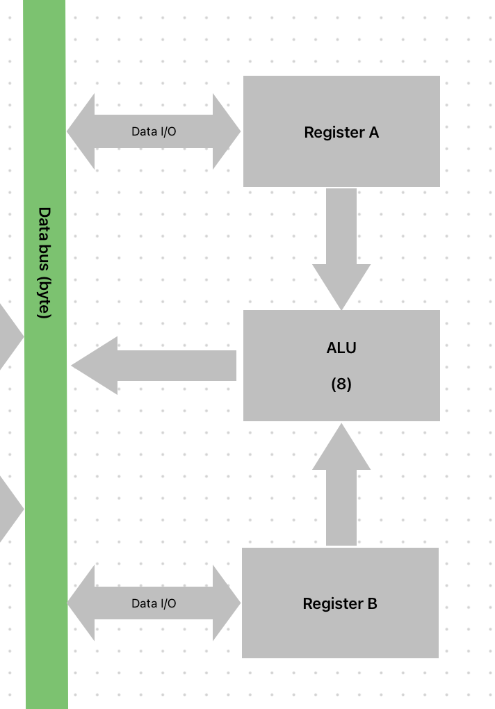
The diagram shows the relationships between the various components. It includes two parts: Registers (which have the property of directly connecting their output to the ALU unit) and the ALU (currently only capable of addition and subtraction).
As just introduced, there are broadly two types of components:
- Registers (Output directly connected to the ALU unit)
- ALU (Currently only addition and subtraction)
Register (A,B)

This section focuses on Register (A,B), accompanied by an image to show its appearance. The design reference is Ben Eater’s Register design, but we made modifications to the bus interface and the internal connection to the ALU, and adjusted the male header pinout. This design is a crucial part, used for storing the two values for addition and subtraction operations.
.
ALU

This section focuses on the ALU, accompanied by an image to show its appearance. The design reference is Ben Eater’s ALU design, but we made modifications to the bus interface and the ALU output for debugging, and adjusted the male header pinout. The ALU (Arithmetic Logic Unit) is a vital part of computer hardware, responsible for processing arithmetic and logical operations. Our ALU currently supports addition and subtraction; these operations use Register A and B to store data during computation.
.
Top-level Breadboard
In the initial implementation process, my primary goal was to avoid using breadboards. However, during implementation, I found myself using perfboards, mounting components using female headers and connecting them. This method, I realized, was fundamentally no distinction from using a breadboard. Consequently, to achieve more efficient circuit operation, I ultimately decided to abandon the perfboard approach and revert to using breadboards for the circuit.
Next Post
During the experimentation process, I realized I was missing a crucial tool: a logic analyzer, which is essential for evaluating the signal input and output of the components I was using. At that time, I didn’t spend much time thinking about this issue. Later, after referencing Ben Eater’s example of using an Arduino as a logic analyzer in his 6502 computer project, I also decided to use an Arduino to build a simple logic analysis tool.
The next post will briefly explain the methods I used, how I utilized Arduino and Processing to build this simple logic analysis tool, and its accompanying software.